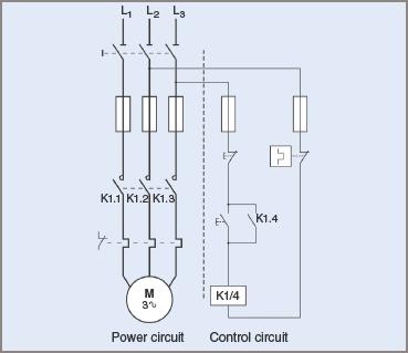
Schematics and wiring diagrams are an integral part of any electrical contractor's work. Understanding how they are used to troubleshoot complex issues is an important skill for anyone in the electrical contracting business. An example of this type of diagram is a 3 phase contactor, which is used to control large electric loads. In this article, we'll take a look at what a 3 phase contactor is and how to read the schematic and wiring diagrams to make sure the system is wired correctly.
A 3 phase contactor is a type of switch used to turn on and off larger electric motors. It contains three sets of coils, each connected to a separate phase of incoming power. When all three phases are energized, the contactor is engaged, providing a path for electricity to flow through to the motor. A wiring diagram is used to show how the contactor is wired to the motor, as well as any other components that may be part of the system. Reading the diagram is an important skill for anyone working with 3 phase systems.
The wiring diagram will typically include the contactor's coil, the motor terminals, and any other switches or devices associated with the system. Once you've identified all of the components, you can trace the various lines on the diagram to see how they're connected. This includes following the paths from the various inputs to the contactor's coils, tracing from the contacts back to the motor, and understanding what function each switch or device performs. With this knowledge, you can be sure that all of the connections are correct and the system is safe to operate.
Overall, reading and understanding a 3 phase contactor's schematic and wiring diagram is a vital part of any electrical contractor's work. Knowing how to properly identify and trace the different components in the system will keep everyone involved safe, reduce troubleshooting time, and help ensure successful project completion.

Contactor Construction Working Principle Types And Differences
Solved A Draw The Power Schematic For Starting 3 Phase Chegg Com

Dol Starter Direct Online Wiring Diagram Working Principle Electrical4u

Main And Auxiliary Circuit Diagrams Of Switching Three Phase Motors Via Contactor Directly Eep

Control Two Motors In Sequence After Time Delay Circuit Operation

Contactors And Relays Construction Operation

Wiring Diagram Contactor Electrical Wires Cable Three Phase Electric Power Save Electricity Electronics Motor Controller Png Pngwing

Three Phase Appliance Protector Detailed Circuit Diagram Available

Three Phase Solid State Relay Project Kit

What Is A Contactor Library Automationdirect Com

3 Phase Wiring Question Start Stop Switch The Home Machinist

Start Stop Circuit What They Are Where And How To Wire

How Can We Switch A Single Phase Motor Forward Reverse And On Off With 6 Pin Quora

Induction Motor Starter Types Circuit Diagram

Contactors Electromechanical Relays Electronics Textbook

Single Phase Motor Connection With Magnetic Contactor Wiring Diagram Electrical And Electronics Technology Degree
A Sketch Of The Electromagnetic Contactor B Magnetic Scientific Diagram

Main And Auxiliary Circuit Diagrams Of Switching Three Phase Motors Via Contactor Directly Eep

Direct Online Starter Dol Motor Circuit Diagram And Working Principle

Grid Mains To Generator Changeover Relay Circuit Homemade Projects
