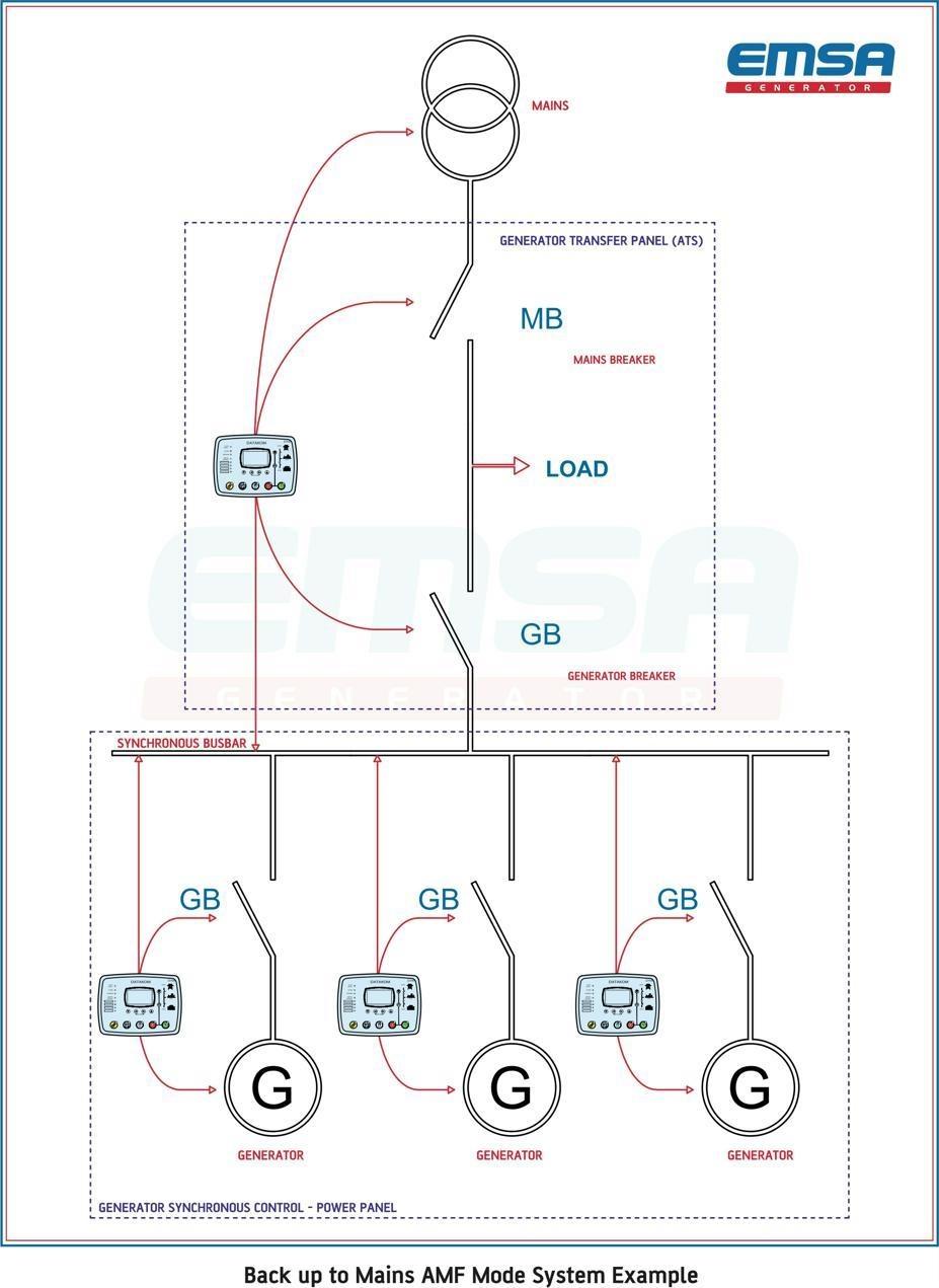
Parallel Generators Diagrams provide a visual representation of the complex connections between components of a parallel generator system. This diagram is essential for any installation, maintenance, or troubleshooting of a parallel generator system. The diagram shows how the different parts of the system are connected together and how they influence each other, so that when something malfunctions, it can be easily identified. As generators become more advanced, the diagrams become more intricate, providing a detailed overview of the system's operation.
The components in a Parallel Generators Diagram are the main generators, auxiliary generators, switchgears, and wires. The main generator is usually located at the central point in the diagram and provides power to the auxiliary generators. Auxiliary generators are generally smaller and provide additional power when the main generator cannot meet the demand. Switchgears are used to disconnect and reconnect the main and auxiliary generators as needed. Wires are used to connect all of the components together in order to ensure that the right amount of power is being delivered to the right place.
Parallel Generators Diagrams can be extremely helpful for anyone who is looking to maintain or install a parallel generator system. They provide a detailed overview of the system's setup and help identify any potential problems before they become major issues. Additionally, the diagrams make it possible to quickly troubleshoot any problems that may occur. With a clear visual representation of the system's connections, it is much easier to pinpoint any issues that arise and make the necessary adjustments. By utilizing Parallel Generators Diagrams, maintainers and installers can save time and resources while ensuring that their systems are running efficiently.


