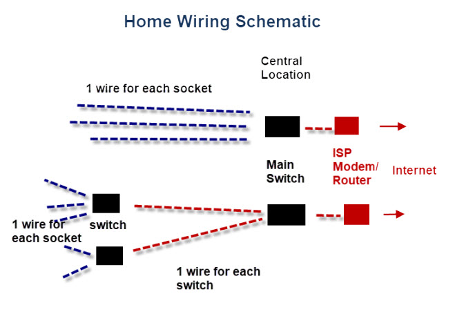
Ethernet Connection Wiring Diagrams are an essential tool for the modern network installer. In the past, Ethernet cables were typically installed in one of several ways, depending on the type of system being hooked up - e.g. a router to a modem, or a switch to a router. Today, Ethernet connections require far more complex wiring diagrams, as the number of different components and configurations has grown exponentially. Understanding how these diagrams work is key to installing a reliable local area network.
For starters, it's important to note that Ethernet cables all use the same basic wiring schemes, regardless of the device being connected. This includes an 8-wire pattern with pins divided into two sets – a Data (D) and a Power (P) set. The top four pins are the Data pins, used to transmit data from one device to another. The bottom four pins are the Power pins, used to provide power to the components in the cable. Each pin must be correctly wired for the connection to work properly.
Your wiring diagram should spell out the exact sequence of pins used, otherwise you may encounter problems later down the line. It's also essential to use the right type of cable when creating an Ethernet connection. For instance, if you're connecting two computers together via a router, then an Ethernet patch cable must be used. This type of cable is specifically designed for this purpose, as it contains both the data and power cables. It's also important to use the correct patch panel when connecting devices to a switch, as this will ensure the connection is secure.
Finally, while wires are important, they aren't the only factor to consider when setting up an Ethernet network. Factors like environment, cable length, and cable quality can also have an impact on how your network performs. With the right wiring diagram and some professional advice, however, setting up a reliable Ethernet connection can be easily achieved.

Medium Dependent Interface Ethernet Crossover Cable Wiring Diagram Angle Text Rectangle Png Pngwing

Ethernet Cable Types Pinout Cat 5 5e 6 6a 7 8 Electronics Notes

What S Correct Order Of Wires Pins For Cat5 Cat6 Cat7 Cat8 Network Patch Ethernet Cable How To Make Rj45 Etc T568a Vs T568b Which One Use Is 8p8c Blog D Without Nonsense
.jpg?strip=all)
Rj45 Colors And Wiring Guide Diagram Tia Eia 568a 568b Brothers Y News Shenzhen Brother Young Development Co Ltd

Rj 45 Ethernet Cable Wiring Diagram Silentway Com

Crossover Cable Vs Ethernet What S The Difference

Wiring A Home Ethernet Network Practical Beginners Guide

Ethernet Cable Wiring Diagram With Color Code For Cat5 Cat6 Etechnog
Cctv Camera Pros Network Cable Wire Diagram Cat5 Cat6 For Standard Ethernet Https Www Cctvcamerapros Com Cat 5 Wiring S 293 Htm Facebook

Network Switch Power Over Ethernet Wiring Diagram Gigabit Png 800x481px Cable Computer

Rj45 Colors Wiring Guide Diagrams

Knowledge Base Simrad How To Design And Build An Ethernet Network Advanced Users

R S C Broadband Supply Co Character Generators

How To Fix Your Ip Security Camera S Damaged Rj45 Ethernet Connection

Ip Camera Ethernet Connection Hot 57 Off Www Ingeniovirtual Com

Ethernet Cable Color Coding Diagram The Internet Centre

Rj45 Wiring
10baset Wiring Procedures

