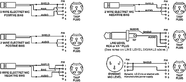
Turner Microphone Wiring Diagrams are invaluable tools for anyone who deals with audio equipment. They allow technicians, DJs, and studio engineers to quickly and accurately identify the types of cables and connectors used in their system. Without these diagrams, it would be nearly impossible to make sense of complicated wiring schemes. With Turner diagrams readily available, you can easily troubleshoot any problems before they cause your setup to crash.
Turner diagrams provide a comprehensive overview of how each component is hooked up. Different types of microphones are denoted by a symbol displayed alongside the cable and connector information. An overall diagram will also illustrate which components are connected, making it much easier to identify the source of a particular problem. The diagrams also show which specific terminal or contact point is being used for a particular connection, ensuring that the correct cables and connectors are used.
Turner diagrams can save technicians hours of time on a single project. They allow for quick and easy identification of components and connections. Without them, troubleshooting could take days instead of hours. This makes Turner diagrams an invaluable piece of equipment for any audio professional. They will help you stay in control of your system so that you can always deliver the best sound possible.

Date
Microphone Wiring Diagrams

In3eci Italian Radio Station
Turner M 2u Wired To 4 Pin On Omegaforce S45 Worldwidedx Radio Forum

Microphone Wiring Diagrams

Turner Co Crystal Mic Amplifier Antique Electronic Supply

Galaxy Dx Radios Dx98vhp Service Manual

Copper Talk Rk56 Mic Switch Wiring

Vintage Turner 454c Ssb Microphone 169036258

Vhf Transmitter 5 Pin Input Jack Wiring
Turner Expander 500 Instructions And Circuit Diagram

Microfiles The Turner 44d Derived From A Distinctly Unique Heritage Prosoundweb

Mike Wiring Guide

Date

Cobra 4 Pin Cb Microphones Com

Rd104e Road Devil Amplified 4 Pin Cb Microphone Com

Anytone At 5555n

Microphone Wiring Diagrams Www Walcottradio Com

Date
