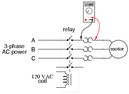
Single Phase Motor Wiring Diagram With Contactor is an essential part of maintaining and repairing industrial machines. It helps mechatronic engineers understand the flow of electricity in a system and enables them to troubleshoot any issues. Contactor relays are commonly used in single phase, three-phase, or combination system applications to control high power loads. A wiring diagram with contactor is a crucial part of understanding the overall operation of the motor system.
The purpose of a wiring diagram with contactor is to provide a better understanding of how the motor system works. This can be used by technicians to ensure proper installation and maintenance of the machine. It shows the electrical path the current takes in and out of the system as well as the points of contact that connect each part. It also describes the function of each wire, component, and connection. A comprehensive wiring diagram will include notes regarding the type of contactors, working voltage, and current carrying capacity.
Wiring diagrams with contactors are typically used for large industrial machines such as pumps, fans, motors, and conveyors. In addition to detailing the overall design of the system, these diagrams also provide a visual representation of the various components and how they interact. As more complex systems become commonplace, it is essential to thoroughly understand the wiring diagrams with contactors. This ensures that everything is properly connected, thus preventing any potential system malfunctions.
To fully utilize a wiring diagram with contactors, it is important to keep the diagram up-to-date. Any changes made to the system should be documented and the diagram updated accordingly. Doing so will ensure that users have the most recent information and help avoid costly repairs or rework. Additionally, understanding and following the diagram will prevent potentially hazardous situations from arising in the first place. Furthermore, having a reliable wiring diagram with contactors can make maintenance and troubleshooting much easier, saving time and money in the long run.

Service Technician Training Electricity For Servicepeople Part 22 Cleaner Times

Interlocking Methods For Reversing Control Basic Circuits

Chapter 4 Electrical Symbols And Diagrams Language Of

Single Phase Motor Wiring Diagram And Examples Wira Electrical

Motor Circuits And Control Applied Electricity
25a Power Contactors Silent With Handle

Main And Auxiliary Circuit Diagrams Of Switching Three Phase Motors Via Contactor Directly Eep

Single Phase Electric Motor Power Induction Xinnuo

1 5cv 230v Single Phase Motor Starter With Contactor Adajusa

Magnetic Starter Wiring An Allen Bradley 709 3 Phase For Single 220v The Hobby Machinist

Motor Circuits And Control Applied Electricity

Capacitor Start Motors Diagram Explanation Of How A Is To Single Phase Motor Bright Hub Engineering

Makky On Twitter Just Pinned To Wiring Diagram Single Phase Motor Contactor Elec Eng World W T Throughout Carlplant Https Co Vh2bo0dadp Xolivraaoi

To Make Test The Working Of Single Phase Preventer Using Contactor Control Free Electrical Notebook Theory And Practical

3 Phase Motor Contactor Wiring Diagram Guide Springer Controls

Aim Manual Page 57 Single Phase Motors And Controls Motor Maintenance North America Water Franklin Electric
Wiring Of Three Phase Motor Scientific Diagram

Control Two Motors In Sequence After Time Delay Circuit Operation

How To Use Vfd For Single Phase Motor Ato Com
03 21 13 1 Of Wiring Diagram 2 Sd Winding Size 0
