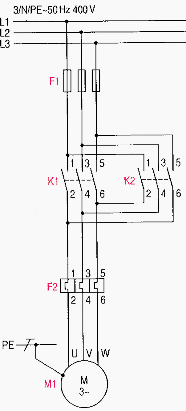
Understanding the basics of a reversing contactor wiring diagram is very important for anyone who is working with electricals in a home or commercial environment. It can be tough to get to grips with but getting a clear understanding of a reversing contactor wiring diagram can make working with such diagrams easier and safer.
A reversing contactor wiring diagram is a diagram that shows how a switch, relay, or motor start capacitor is wired to reverse the direction of current flow. It’s usually used to describe the connection between two or more devices, such as an electrical outlet or a motor. This type of diagram is also known as a “reversing control circuit” because it shows how a motor or other device is controlled by a switch or other control device.
The basic structure of a reversing contactor wiring diagram consists of three parts: the power source, the load, and the control. The power source provides the source of electricity needed to run the switch, relay, or motor start capacitor. The load is the device that will be reversed and can include a motor, a light fixture, or an appliance. The control is the switch or other control device used to activate the reversing process. When the switch or other control is activated, the flow of electricity is reversed, which in turn reverses the current in the load.
By being able to interpret a reversing contactor wiring diagram, you will be able to ensure that the electrical system you are working with is safe and properly wired. Not only will this add a layer of safety to your work, but it will also make your job simpler, as you won’t need to guess at what kind of wiring is needed. With a clear understanding of this type of wiring diagram, you can confidently complete any project that requires it.
Control Wiring Diagram Motor J C Electrical Company Ltd Facebook

3 Phase Motor Reversing With Delay And Limit Switches Doityourself Com Community Forums

100a Dc Motor Reversing Contactor 12v 24v 48v 2no 2nc

Schneider Electric Lc2k12004b7 Reversing Contactor Combo 1 Pc S Conrad Com

400a Dc Reversing Contactor 2 Pole 12v 24v 48v Ato Com

Page 923 Motor Protection And Control Manual Starters Contactors Overload Relays
Reversing Contactor Assembly Dc Coil External Interlock With Power And Auxiliary Wiring 9a Ac3 In 4kw Voltage 24vdc Lovato Electric
Lp2k0901bd Schneider Electric Tesys K Lp2k Reversing Contactor 24 V Dc Coil 3 Pole 9 A 4 Kw 3no Rs Components

36v Txt Sr48500 Sw202 7126 Motor No Reverse Intermittent Page 2

Reversing Contactor Definition Advantages And Connection Diagrams

Main And Auxiliary Circuit Diagrams Of Switching Three Phase Motors Via Contactor Directly Eep
Coffing Ujc Qxd

400a Reversing Contactor Dpdt Electric Car Parts Co

Interlocking Methods For Reversing Control Basic Circuits

Electric Reverse Solutions Diy Car Forums
Untitled

Reversing Contactor Definition Advantages And Connection Diagrams
275 Series Motor Reversing Contactor 2x 3pst 15 Amp


