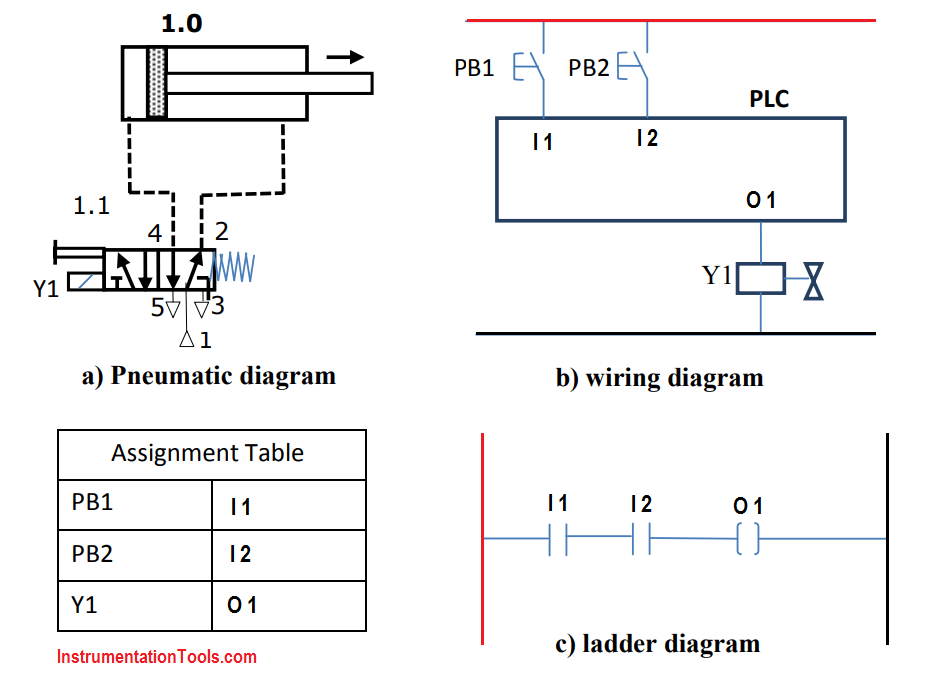
The double-acting pneumatic cylinder is an essential component in industrial systems, providing efficient linear motion with precise speed and force. A pneumatic circuit diagram for a double-acting cylinder includes a number of components, which must be connected in a particular way in order to create a working system. This article explains the main parts of this kind of system and how they interact with each other.
The most significant element of any pneumatic circuit diagram for a double-acting cylinder is the pressure regulator. This component is what allows the user to adjust the air pressure that will be used to actuate the cylinder. It can be set to produce a steady constant pressure, or it can be used to create a pressure differential - one for extension and a second for retraction of the piston inside the cylinder. Additionally, the regulator also controls the release of air, allowing it to build up or dissipate as needed.
The next important element on a pneumatic circuit diagram for a double-acting cylinder is the directional valve. This component is responsible for controlling the direction of airflow and for determining when the cylinder will move and by how much. The valve is typically divided into two sections – one section controls the direction of airflow, while the other controls the speed at which the air is released. This valve might be operated manually, or it might be automated using an electronic controller.
Finally, the last component on a pneumatic circuit diagram for a double-acting cylinder is the air tank. This component stores the air that powers the cylinder, allowing it to work without interruption. An air tank is also important for ensuring that the pressure stays consistent, which is critical for accurate performance.
In conclusion, a pneumatic circuit diagram for a double-acting cylinder includes three main components: a pressure regulator, a directional valve, and an air tank. They are responsible for adjusting and controlling the pressure, direction, and flow of air to ensure that the cylinder works as efficiently and accurately as possible. Properly connecting and setting up these components is essential for creating a successful system.
Pneumatic Systems

20 Direct Control System With A Double Acting Cylinder 1a Is Scientific Diagram

Solved 1 Figure Shows A Pneumatic Circuit Diagram To Chegg Com

Simulation Diagram Of Double Acting Pneumatic Cylinder Scientific

Plc Pneumatic Circuit Control Programming System

Solved Exercisel Design The Equivalent Pneumatic Circuit Diagram And Label All Devices Spts Double Acting Cylinder Is To Advance When Push On Operated Upon Release Of

Pneumatic Circuit Archives Upmation

Basic Pneumatic Circuits Part 2 Of Modern Pumping Today

Pneumatic Systems

Double Acting Pneumatic Actuator Scientific Diagram

Explain Pneumatic Circuit For Sd Control Of Single Acting Cylinder With Neat Sketch Mechanical Engg Diploma Simple Notes Solved Papers And S

The Schematic Diagram Of Electro Pneumatic Circuit In Hsm Scientific
Solved 1 B Figure Shows A Pneumatic Circuit Diagram Chegg Com
Solved Task 1 Draw The Sd Regulation Of A Double Chegg Com

Direct And Indirect Control Of Single Acting Double Air Cylinders Motors Mechanical Engg Diploma Topicwise Notes Solutions

Plc Pneumatic Circuit Control Programming System

Double Acting Pneumatic Actuator Scientific Diagram

Hold It Right There Methods For Stopping A Linear Pneumatic Actuator S Movement In Mid Stroke Fluid Power Journal

5 2 Way Pneumatic Solenoid Valve For Double Acting Cylinder

4 Basic Pneumatic Circuits Power Motion

