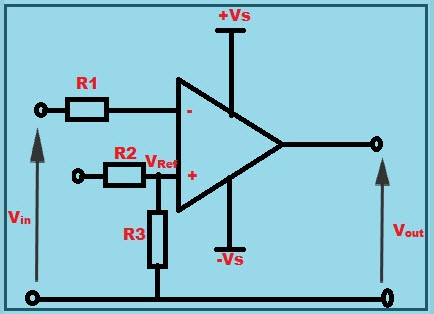
An electronic comparator circuit is a device used to measure and compare two electrical signals and output the greater of the two signals. This is useful in a variety of applications, ranging from noise cancellation to signal amplification. Comparator circuits can be found in many different electronic products, including consumer products and industrial products like medical instruments and machinery. Understanding how to use and troubleshoot a comparator circuit is important in order to ensure proper functioning of your device.
First, you need to understand the basic components of a comparator circuit. The most important components are the op-amp, the reference voltage source, and the output. The op-amp amplifies any differences between the two input signals, and its output is compared to the reference voltage. When the op-amp's output is higher than the reference voltage, the comparator circuit will output the higher of the two input signals.
Next, you need to connect all of the components properly and correctly. This involves connecting the inputs and outputs to the correct pins on the op-amp and then connecting the reference voltage source. Once everything is connected, the comparator circuit is ready to be tested. You can do this by measuring the output voltage at various points throughout the circuit. If the output voltage matches the reference voltage, then the comparator circuit is working properly.
Finally, you need to know how to troubleshoot the comparator circuit if it does not work as expected. This involves measuring the output voltage and input signals to determine where the issue might be. This can sometimes be difficult to do without a specialized meter, but there are steps you can take to debug the comparator circuit. Firstly, you should check to make sure that none of the components are shorted out and that the reference voltage is correct. Then, you should make sure that the op-amp is properly compensated and that the input signals are within the correct range. After ensuring these things, the comparator circuit should be functional and able to compare two input signals and output the greater of the two signals.
Using a comparator circuit is an essential skill for anyone who designs or works with electronics. By understanding the components of a comparator circuit and how to connect them correctly, as well as how to troubleshoot any issues that may arise, anyone can ensure that their devices and instruments are working correctly.

Activity Temperature Control Using Window Comparator Analog Devices Wiki

Dictionary Of Electronic And Engineering Terms Operational Amplifier Window Comparator Circuits

A Comparator Circuit Using Lm 311 Scientific Diagram

Curing Comparator Inility With Hysteresis Analog Devices

Comparators

Voltage Comparator Using Opamp Inverting Non Practical Circuit

Comparator As A Duty Cycle Controller Analog Integrated Circuits Electronics Tutorial

Window Comparator Circuits Tutorial

Comparator Circuits Using Ic 741 311 339 Homemade Circuit Projects 2022

Intro To Amplifier Comparator Circuits Lm311 Lm393 Lm2903 And Lm2901 Hackernoon

Op Amp As Comparator Circuit Working Its Appliations

비교기 회로의 동작 네이버 블로그

How To Use An Op Amp As A Comparator Circuit Homemade Projects

The Simple Comparator And Its Application To Temperature Controller Forum For Electronics

Comparator Circuit Help General Electronics Arduino Forum

How To Build A Voltage Comparator Circuit With An Lm393

Voltage Comparator Circuit Using Opamps Hackatronic

Using An Op Amp As A Comparator Edn
Circuit060084 Design Tool Ti Com
