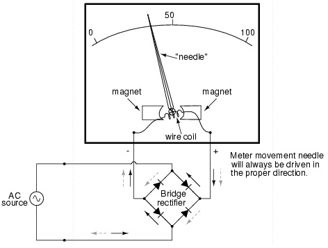
Ammeter circuit diagrams are essential in understanding the electrical components of circuit systems. Ammeters are used to measure current flow, and they are an invaluable tool in the electrical engineering industry. A circuit diagram is the visual representation of a complete electric circuit. It is used to show the physical layout of the components and their interconnections.
The ammeter is a device that measures current in the circuit and connects directly to the circuit. It measures the current in amps (A) or milliamps (mA). The ammeter connection is essential for accurately measuring and monitoring the amount of current flowing through the circuit. Many circuit diagrams will include an initial ammeter connection that is drawn as a dashed line followed by the ammeter symbol, often with the units of measurements (amps or mA) printed along the ammeter connection line.
The first step in reading an ammeter circuit diagram is to identify the components connected to the ammeter. It is important to take note of the specific polarities of the components as this will help you determine the correct direction of the current flow. Once you have identified the components connected to the ammeter, you can begin to interpret the diagram. When looking at the diagram, it is important to note which wires are connected to the left side of the ammeter and which are connected to the right side of the ammeter. The direction of current flow on the wires is usually depicted in the diagram by arrows. The amount of current measured by the ammeter depends on the resistance of the circuit and the applied voltage.
Understanding ammeter circuit diagrams can be complex, but with practice and some patience, you can gain a strong familiarity with them. By closely studying the components, their connection lines, and the direction of the arrows, you can become proficient in interpreting the ammeter circuit diagrams. This knowledge can help you make accurate predictions about how a circuit system will behave and also help you identify potential problems. As such, being able to interpret ammeter circuit diagrams correctly is an invaluable skill for any electrical engineer.

Ammeter Circuit Wiring Diagram

Ammeter Design

Digital Multimeter Circuit Using Icl7107

Electronic Voltmeter Ammeter Circuit Pic16f876 Lcd Picbasic Electronics Projects Circuits

8 5 Ammeter Impact On Measured Circuit

Difference Between Ammeter Voltmeter With Comparison Chart Circuit Globe

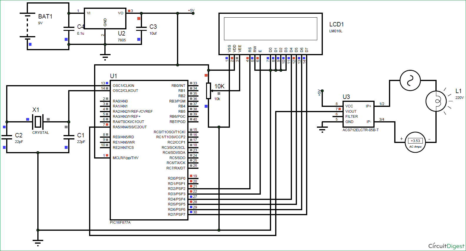
Digital Ammeter Circuit Using Pic Microcontroller And Acs712

Ammeter Electric Cur Wiring Diagram Wikipedia Electrical Network Flow Angle White Png Pngegg

Voltmeter Ammeter Lcd Panel Electronics Lab Com
Micro Ampere Meter Circuit Using Ua 741

Solved 20 In The Circuit Diagram Shown Below Ammeter A1 Chegg Com

18 2 Parallel Circuits Series And Siyavula

A An Equivalent Circuit Of The Ammeter In Fig 1 B Simplified Scientific Diagram

Ammeter Voltmeter Transducer Meters Wire Diagram

An Ammeter And A Rheostat Are Connected In Series Voltmeter Is Scientific Diagram

Electrical Meters

Pico Ammeter Under Meters Circuits 12647 Next Gr

Electronic Voltmeter Ammeter Circuit Using Single Ic 741 Under Repository Circuits 24855 Next Gr
Working Voltmeters And Ammeters Circuitlab Support Forum
